نمای طراحی اسناد مدل موجود را ویرایش می کند.
هنگامی که روبان فعال است ، این دستور زبانه متنی روبان Drawing View Editor را نشان می دهد . وقتی روبان فعال نیست ، از خط فرمان استفاده کنید تا خصوصیات نمای را برای ویرایش تغییر دهید.
با اجرای این دستور پیام های زیر نمایش داده می شود.
نمای طراحی را برای ویرایش مشخص می کند.
انواع نمایندگی را مشخص می کند تا بتواند نمایشی را که می خواهید در نمای نقشه انتخاب شده نشان دهید انتخاب کنید. نمایندگی ها فقط توسط مدل های Inventor پشتیبانی می شوند .
توجه داشته باشید:
نمای نمای طراحی را برای نمایش در نمای نقاشی انتخاب شده انتخاب می کند. وارد ؟ برای نمایش لیستی از نمایشهای طراحی موجود.
این گزینه فقط درصورتی موجود است که نمای نقاشی انتخاب شده از مجموعه مخترعین (* .iam) ایجاد شده باشد که حاوی نمای طراحی است.
یک نمایه موقعیتی را برای نمایش در نمای نقشه انتخاب شده انتخاب می کند. وارد ؟ برای نمایش لیستی از نمایش های موجود. این گزینه فقط درصورتی موجود است که نمای نقاشی انتخاب شده از مجموعه مخترعین (* .iam) ایجاد شده باشد که حاوی بازنمایی های موقعیتی است.
سطح نمایش جزئیات را برای نمایش در نمای نقشه انتخاب شده انتخاب می کند. وارد شوید ؟ برای نمایش لیستی از نمایش های موجود. این گزینه فقط درصورتی موجود است که نمای نقاشی انتخاب شده از مجموعه مخترعین (* .iam) ایجاد شود.
حالت جوش را برای نمایش در نمای نقشه انتخاب شده انتخاب می کند. وارد ؟ برای نمایش لیستی از حالت های جوشکاری و قطعات در حالت آماده سازی. حالت مجمع جوشکاری را قبل از هرگونه عمل بر روی آن نشان می دهد. حالت Welds بعد از انجام جوشکاری مونتاژ را نشان می دهد. حالت ماشینکاری بعد از انجام عملیات جوشکاری ، جوشکاری را نشان می دهد. حالت آماده سازی به صراحت ذکر نشده است. با این حال ؟ گزینه نام اجزای موجود در حالت آماده سازی قبل از جوشکاری را لیست می کند. نمایندگی جوش فقط درصورتی موجود است که نمای نقاشی انتخاب شده
از مونتاژ جوش مخترع (* .iam) ایجاد شده باشد.
عضوی را از یک کارخانه iAssociation یا کارخانه iPart انتخاب می کند تا در نمای نقشه انتخاب شده نشان داده شود. وارد ؟ برای نمایش لیستی از اعضای موجود. این گزینه فقط درصورتی موجود است که نمای نقاشی انتخاب شده از یک کارخانه iAssemble یا کارخانه iPart (* .iam ، * .ipt) ایجاد شود.
نمای فلزی را برای نمایش در نمای نقاشی انتخاب شده انتخاب می کند. وارد ؟ برای نمایش لیستی از گزینه های موجود. این گزینه فقط درصورتی موجود است که نمای نقاشی انتخاب شده از یک کارخانه iAssemble یا کارخانه iPart (* .iam ، * .ipt) ایجاد شود.
نمای نمایش را برای نمایش در نمای نقاشی انتخاب شده انتخاب می کند. وارد ؟ برای نمایش لیستی از نمایش های موجود. این گزینه فقط در دسترس است که نمای طراحی شده از یک سند ارائه دهنده Inventor (* .ipn) ایجاد شده است.
شیوه نمایش را برای استفاده برای نمای پایه مشخص می کند.
مقیاس مطلق را برای استفاده برای نمای نقشه انتخاب شده مشخص می کند. برای تغییر مقیاس ، مقیاس استاندارد را از لیست کشویی انتخاب کنید یا مستقیماً مقیاس غیر استاندارد را وارد کنید . به طور پیش فرض ، نمایش های پیش بینی شده و مقطعی همان مقیاس والدین خود را به ارث می برند.
نماهای جزئیات یک مقیاس بالاتر از مقیاس نمایش والدین است.
گزینه های دید را برای تنظیم برای نمای پایه مشخص می کند.
لبه های تداخل را روشن یا خاموش می کند. لبه تداخل هنگامی رخ می دهد که چهره های چندین مؤلفه از هم جدا شوند. هنگامی که لبه های تداخل روشن هستند ، لبه ای نمایش داده می شود که محل اجزای آنها در کجا ملاقات می کند. لبه تداخل هنگامی رخ می دهد که چهره های چندین مؤلفه از هم جدا شوند. هنگامی که لبه های تداخل روشن هستند ، لبه ای نمایش داده می شود که محل اجزای آنها در کجا ملاقات می کند.
لبه های مماس را روشن یا خاموش می کند. لبه های مماس انتقال بین یک سطح صاف و یک لبه گرد را نشان می دهد ، که معمولاً به عنوان لبه های پر شده مشاهده می شود.
خطوط میزان خم ورق فلز را روشن یا خاموش می کند. خطوط اندازه خم فلزی نشانگر موقعیت گذار که در آن یک خم لولا یا چین خورده است ، در یک
نمای فلز مسطح شده است. این گزینه فقط در صورتی موجود است که مدل مربوطه دارای یک صفحه فلزی مسطح باشد که در آن مشخص شده است.
قابلیت روشن یا خاموش بودن خطوط نخ را در پیچ ها و سوراخ های ضبط شده نشان می دهد.
قابلیت مشاهده مسیرهای ارائه را روشن یا خاموش می کند. مسیرهای ارائه خطوط در نمای منفجر شده (در یک فایل ارائه) هستند که مسیری را نشان می دهند که در طی آن اجزاء به موقعیت مونتاژ منتقل می شوند.
مشخص می کند که آیا روش پیش بینی شده در نمای بخش متعامد است. توجه: این گزینه فقط برای نمایش بخش ها در دسترس است.
عمق خط بخش را مشخص می کند یا خیر.
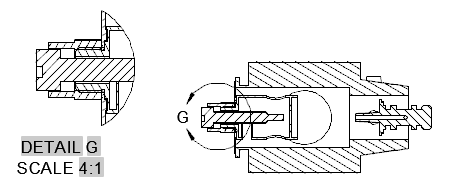
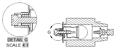
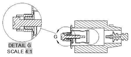
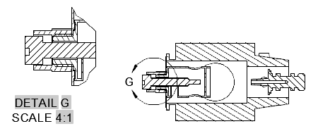
مشخص می کند که مرز نمایش جزئیات مدور یا مستطیل است یا خیر. مرز پیش فرض دایره ای است.
سبک مدل لبه برای مدل نمای جزئیات را مشخص می کند.
مشخص می کند که دریچه در قسمت انتخاب شده نمایش داده شده است یا نمای جزئیات.
به قسمت قبلی باز می گردد ، یا بسته به مکانی که در چرخه فرمان باشد گزینه ظاهر می شود ، فرمان را تکمیل می کند.
Edits an existing model documentation drawing view.
When the ribbon is active, this command displays the Drawing View Editor ribbon contextual
tab. When the ribbon is not active, use the command line to change the properties
of the view to edit.
The following prompts are displayed.
Specifies the drawing view to edit.
Specifies the representation types to enable you to select the representation you
want to show in the selected drawing view. Representations are supported only by Inventor
models.
NOTE:
Selects a design view representation to show in the selected drawing view. Enter ?
to display a list of available design views.
This option is available only if the selected drawing view is created from an Inventor
assembly (*.iam) that contains design view representations.
Selects a positional representation to show in the selected drawing view. Enter ?
to display a list of available representations.
This option is available only if the selected drawing view is created from an Inventor
assembly (*.iam) that contains positional representations.
Selects a level of detail representation to show in the selected drawing view. Enter
? to display a list of available representations.
This option is available only if the selected drawing view is created from an Inventor
assembly (*.iam).
Selects the weldment state to show in the selected drawing view.
Enter ? to display a list of weldment states and components in preparatory state.
The Assembly state shows the weldment prior to any operation are performed on it.
The Welds state shows the assembly after welding is performed. The Machining state
shows the weldment after post welding machining is performed. The Preparation state
is not explicitly listed. However, the ? option lists the names of the components
in the pre-welding preparatory state.
The weldment representation is available only if the selected drawing view is created
from an Inventor weldment assembly (*.iam).
Selects a member from an iAssembly factory or iPart factory, to show in the selected
drawing view. Enter ? to display a list of available members.
This option is available only if the selected drawing view is created from an iAssembly
factory or an iPart factory (*.iam, *.ipt).
Selects the sheet metal view to show in the selected drawing view. Enter ? to display
a list of available options.
This option is available only if the selected drawing view is created from an iAssembly
factory or an iPart factory (*.iam, *.ipt).
Selects the presentation view to show in the selected drawing view. Enter ? to display
a list of available views.
This option is available only the selected drawing view is created from an Inventor
Presentation document (*.ipn).
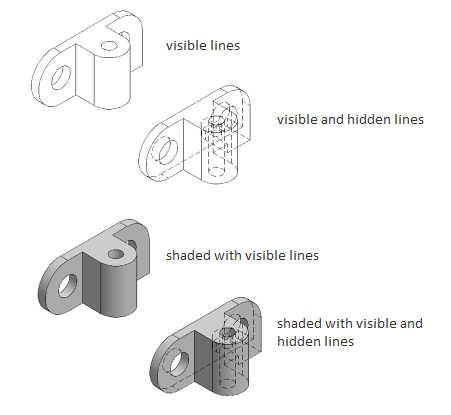
Specifies the display style to use for the base view.
Specifies the absolute scale to use for the selected drawing view. To change the scale,
select a standard scale from the drop-down list, or directly enter a non-standard
scale.
By default, projected and section views inherit the same scale as their parent; detail
views are one scale higher than the parent view scale.
Specifies the visibility options to set for the base view.
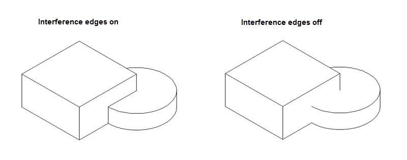
Turns visibility of interference edges on or off. An interference edge occurs when
faces of multiple components intersect. When Interference Edges are turned on, an
edge is displayed that shows where the components meet.
An interference edge occurs when faces of multiple components intersect. When Interference
Edges are turned on, an edge is displayed that shows where the components meet.
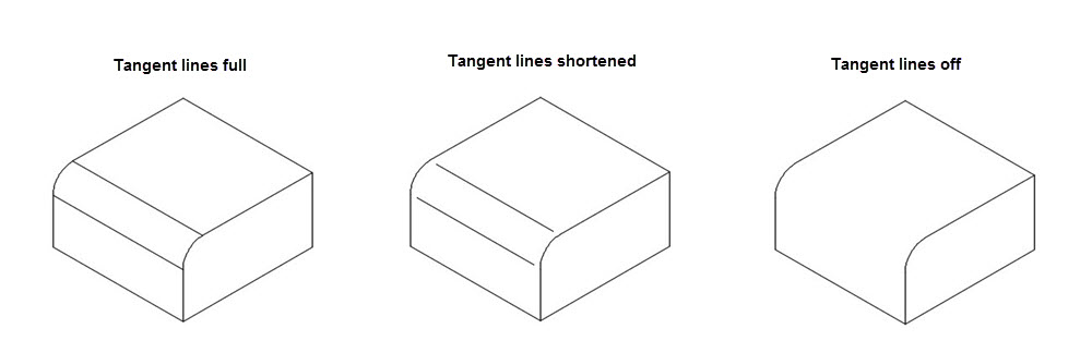
Turns visibility of tangent edges on or off. Tangent edges mark the transition between
a flat surface and a rounded edge, most commonly seen as filleted edges.
Turns visibility of sheet metal bend extent lines on or off. Sheet metal bend extent
lines indicate the location of transition about which a bend hinges or folds, in a
flattened sheet metal view.
This option is available only if the corresponding model has a flattened sheet metal
view defined in it.
Turns visibility of thread lines on screws and tapped holes, on or off.
Turns visibility of presentation trails on or off. Presentation trails are lines in
an exploded view (in a presentation file) that show the direction along which a components
are moved into assembled position.
Specifies if the projected method of the section view is orthogonal.
Specifies if the depth of the section line.
Specifies if the detail view boundary is circular or rectangular. The default boundary
is circular.
Specifies the style for the edge for the detail view model.
Specifies if hatch is displayed in the selected section or detail view.
Goes back to the previous prompt, or completes the command, depending on where in
the command cycle the option appears.