نمای پایه را از فضای مدل یا مدلهای مخترع Autodesk ایجاد می کند.
با اجرای این دستور پیام های زیر نمایش داده می شود.
در فضای مدل ، اشیاء جداگانه را انتخاب می کنید یا همه مواد جامد و سطوح را انتخاب می کنید. در طرح ، برنامه کلیه مواد جامد و سطوح موجود در فضای مدل را انتخاب می کند و شما مکان را برای نمای پایه مشخص می کنید.
کادر گفتگوی Select File را باز می کند.
(فقط در صورتی که در فضای مدل هستید) موجود است
یک طرح را برای نمایش نماهای پایه مشخص می کند. تو می توانی
اگر فضای مدل حاوی مواد جامد و سطحی قابل مشاهده نباشد ، کادر گفتگوی Select File نمایش داده می شود تا شما را قادر به انتخاب مدل Inventor کنید. نمای پایه شامل کلیه مواد جامد و سطوح موجود در فضای مدل است. با استفاده از گزینه Select می توانید مواد جامد و سطوح را از نمای پایه حذف کنید.
مشخص می کند که شما می خواهید از همه مواد جامد و سطوح در فضای مدل استفاده کنید.
در قسمت نقشه ، محل نمای پایه را مشخص کنید.
مشخص می کند که دستور بعد از ایجاد نمای پایه خارج می شود یا برای ایجاد نماهای پیش بینی شده ادامه می یابد یا خیر .
اشیاء را برای اضافه کردن یا حذف کردن مشخص می کند.
انواع نمایندگی را نشان می
دهد تا بتواند نمایشی را که می خواهید در نمای پایه نشان دهید انتخاب کنید.
توجه داشته باشید:
نمای نمای طراحی را برای نمایش در نمای پایه انتخاب می کند. وارد ؟ برای نمایش لیستی از نمایشهای طراحی موجود.
این گزینه فقط در صورت ایجاد نمای پایه از مجموعه مخترعین (* .iam) موجود است که حاوی نمای طراحی است.
یک نمایه موقعیتی را برای نمایش در نمای پایه انتخاب می کند. وارد ؟ برای نمایش لیستی از نمایش های موجود. این گزینه فقط در صورت ایجاد نمای پایه از مجموعه مخترعین (* .iam) که حاوی بازنمایی های موقعیتی است ، در دسترس است.
سطح نمایش جزئیات را برای نمایش در نمای پایه انتخاب می کند. وارد ؟ برای نمایش لیستی از نمایش های موجود. این گزینه فقط در صورت ایجاد نمای پایه از مجموعه مخترعین (* .iam) در دسترس است.
حالت جوش را برای نمایش در نمای پایه انتخاب می کند. وارد ؟ برای نمایش لیستی از حالت های جوشکاری و قطعات در حالت آماده سازی. حالت مجمع جوشکاری را قبل از هرگونه عمل بر روی آن نشان می دهد. حالت Welds بعد از انجام جوشکاری مونتاژ را نشان می دهد. حالت ماشینکاری بعد از انجام عملیات جوشکاری ، جوشکاری را نشان می دهد. حالت آماده سازی به صراحت ذکر نشده است. با این حال ؟ گزینه نام اجزای موجود در حالت آماده سازی قبل از جوشکاری را لیست می کند. نمایندگی جوش فقط در صورت ایجاد نمای پایه از مونتاژ جوش مخترع (* .iam) در دسترس است.
عضوی را از یک کارخانه iAssemble یا کارخانه iPart برای نمایش در نمای پایه انتخاب می کند. وارد ؟ برای نمایش لیستی از اعضای موجود.
نمای فلزی را برای نمایش در نمای پایه انتخاب می کند. وارد ؟ برای نمایش لیستی از گزینه های موجود. این گزینه فقط در صورت ایجاد نمای پایه از یک پرونده فلزی Inventor (* .ipt) در دسترس است.
نمای نمایش را برای نمایش در نمای پایه انتخاب می کند. وارد ؟ برای نمایش لیستی از نمایش های موجود. این گزینه فقط در صورت وجود مدل انتخابی یک سند ارائه Inventor (* .ipn) است.
جهت گیری جهت استفاده برای نمای پایه را مشخص می کند. برای استفاده از همان جهت گیری برای مدل مانند فضای مدل ، می توانید گزینه فعلی را انتخاب کنید. در غیر این صورت ، شما یکی از جهت های از پیش تعیین شده زیر را انتخاب می کنید:
شیوه نمایش را برای استفاده برای نمای پایه مشخص می کند.
مقیاس مطلق را برای استفاده برای نمای پایه مشخص می کند. نماهای پیش بینی شده به دست آمده از این نمای به طور خودکار از مقیاسی که تعیین کرده اید به ارث می برند.
گزینه های دید را برای تنظیم برای نمای پایه نشان می دهد. گزینه های قابلیت مشاهده شیء مدل خاص هستند و ممکن است برخی از گزینه ها در مدل انتخابی در دسترس نباشند.
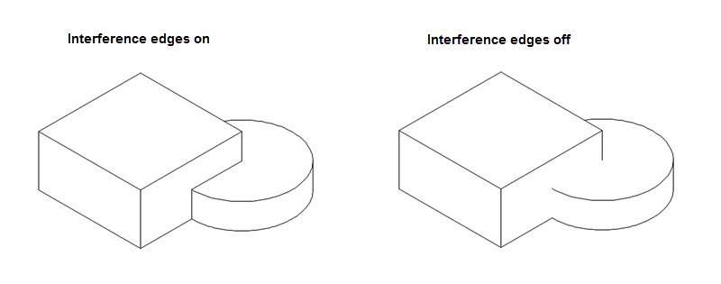
لبه های تداخل را روشن یا خاموش می کند. لبه تداخل هنگامی رخ می دهد که چهره های چندین مؤلفه از هم جدا شوند. هنگامی که لبه های تداخل روشن هستند ، لبه ای نمایش داده می شود که محل اجزای آنها در کجا ملاقات می کند. لبه تداخل هنگامی رخ می دهد که چهره های چندین مؤلفه از هم جدا شوند. هنگامی که لبه های تداخل روشن هستند ، لبه ای نمایش داده می شود که محل اجزای آنها در کجا ملاقات می کند.
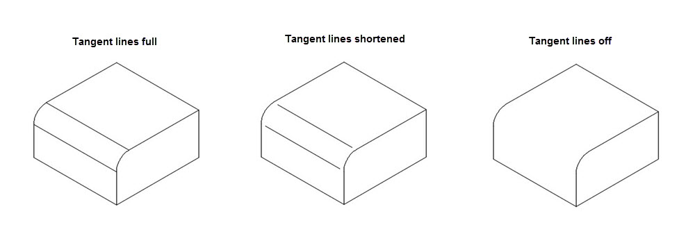
لبه های مماس را روشن یا خاموش می کند. لبه های مماس انتقال بین یک سطح صاف و یک لبه گرد را نشان می دهد ، که معمولاً به عنوان لبه های پر شده مشاهده می شود.
خطوط میزان خم ورق فلز را روشن یا خاموش می کند. خطوط اندازه خم فلزی نشانگر موقعیت گذار که در آن یک خم لولا یا چین خورده است ، در یک
نمای فلز مسطح شده است. این گزینه فقط در صورتی موجود است که مدل مربوطه دارای یک صفحه فلزی مسطح باشد که در آن مشخص شده است.
قابلیت دید خطوط نخ را در پیچ ها و سوراخ های ضبط شده را روشن یا خاموش می کند.
قابلیت مشاهده مسیرهای ارائه را روشن یا خاموش می کند. مسیرهای ارائه خطوط در نمای منفجر شده (در یک فایل ارائه) هستند که مسیری را نشان می دهند که در طی آن اجزاء به موقعیت مونتاژ منتقل می شوند.
پس از قرار گرفتن در منطقه ترسیم ، بدون ایجاد مجبور شدن برای خروج از فرمان ، نمای پایه را حرکت می دهد .
در منطقه ترسیم ، مکان نمای پیش بینی شده را مشخص می کند.
به قسمت قبلی باز می گردد ، یا بسته به مکانی که در چرخه فرمان باشد گزینه ظاهر می شود ، فرمان را تکمیل می کند.
Creates a base view from model space or Autodesk Inventor models.
A base view is the first view created in a drawing. All other views are derived from
the base view.
The base view includes all visible solids and surfaces within model space. If model
space does not contain any visible solids or surfaces, the Select File dialog box
is displayed to enable you to select an Inventor Model.
When the ribbon is active, this command displays the Drawing View Creation ribbon
contextual tab. When the ribbon is not active, use the VIEWEDIT command to change
the properties of the base view.
The following prompts are displayed.
In model space, you select individual objects or select all solids and surfaces.
In layout, the program selects all solids and surfaces available in model space and
you specify the location for the base view.
Opens the Select File dialog box.
(Available only if you are in model space)
Specifies a layout to display the base views. You can
If model space does not contain any visible solids or surfaces, the Select File dialog
box is displayed to enable you to select an Inventor Model.
The base view contains all available solids and surfaces in model space. You can exclude
solids and surfaces from the base view using the Select option.
Specifies that you want to use all solids and surfaces in model space.
In the drawing area, specifies the location of the base view.
Specifies if the command exits after creating the base view or goes on to create projected
views.
Specifies objects to add or remove.
Removes specified objects from the selection set and reopens the previous layout.
Displays representation types to enable you to select the representation you want
to show in the base view.
NOTE:
Selects a design view representation to show in the base view. Enter ? to display
a list of available design views.
This option is available only if you are creating a base view from an Inventor assembly
(*.iam) that contains design view representations.
Selects a positional representation to show in the base view. Enter ? to display a
list of available representations.
This option is available only if you are creating a base view from an Inventor assembly
(*.iam) that contains positional representations.
Selects a level of detail representation to show in the base view. Enter ? to display
a list of available representations.
This option is available only if you are creating a base view from an Inventor assembly
(*.iam).
Selects the weldment state to show in the base view.
Enter ? to display a list of weldment states and components in preparatory state.
The Assembly state shows the weldment prior to any operation are performed on it.
The Welds state shows the assembly after welding is performed. The Machining state
shows the weldment after post welding machining is performed. The Preparation state
is not explicitly listed. However, the ? option lists the names of the components
in the pre-welding preparatory state.
The weldment representation is available only if you are creating a base view from
an Inventor weldment assembly (*.iam).
Selects a member from an iAssembly factory or iPart factory, to show in the base view.
Enter ? to display a list of available members.
Selects the sheet metal view to show in the base view. Enter ? to display a list of
available options.
This option is available only if you are creating a base view from an Inventor sheet
metal file (*.ipt).
Selects the presentation view to show in the base view. Enter ? to display a list
of available views.
This option is available only when the selected model is an Inventor presentation
document (*.ipn).
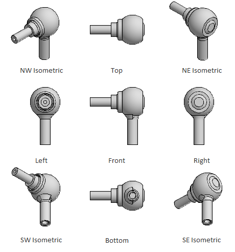
Specifies the orientation to use for the base view.
To use the same orientation for the model as in model space, you can choose the current
option. Otherwise, you the choose from the following preset orientations:
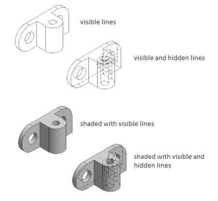
Specifies the display style to use for the base view.
Specifies the absolute scale to use for the base view. Projected views derived from
this view automatically inherit the scale you specify.
Displays the visibility options to set for the base view. Object visibility options
are model specific and some options may not be available in the selected model.
Turns visibility of interference edges on or off. An interference edge occurs when
faces of multiple components intersect. When Interference Edges are turned on, an
edge is displayed that shows where the components meet.
An interference edge occurs when faces of multiple components intersect. When Interference
Edges are turned on, an edge is displayed that shows where the components meet.
Turns visibility of tangent edges on or off. Tangent edges mark the transition between
a flat surface and a rounded edge, most commonly seen as filleted edges.
Turns visibility of sheet metal bend extent lines on or off. Sheet metal bend extent
lines indicate the location of transition about which a bend hinges or folds, in a
flattened sheet metal view.
This option is available only if the corresponding model has a flattened sheet metal
view defined in it.
Turns visibility of thread lines on screws and tapped holes on or off.
Turns visibility of presentation trails on or off. Presentation trails are lines in
an exploded view (in a presentation file) that show the direction along which a components
are moved into assembled position.
Moves the base view, after it is placed in the drawing area, without forcing you to
exit the command.
In the drawing area, specifies the location of the projected view.
Goes back to the previous prompt, or completes the command, depending on where in
the command cycle the option appears.