انتخاب پلی لاین 2D (PEDIT)
انتخاب پلی لاین 2D گزینه های تخصصی PEDIT را ارائه می دهد.
با فشار دادن کلید Ctrl هنگام کلیک بر روی آن ، می توانید یک قطعه یا یک خط قوس یا خط ، که به عنوان یک موضوع فرعی نیز خوانده می شود ، انتخاب کنید. (در اتوکد LT موجود نیست).
اگر پلی النی که انتخاب کردید یک پلی لاین بسته است ، Open گزینه گزینه Close را در قسمت سریع جایگزین می کند. اگر نرمال بودن آن موازی و در همان جهت با محور Z UCS فعلی باشد می توانید یک پلی لاین 2D ویرایش کنید .
پیام های زیر نمایش داده می شود.
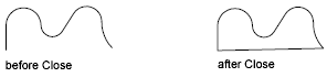
نزدیک
بخش بسته شدن پلی لاین را ایجاد می کند ، آخرین بخش را با قسمت اول متصل می کند. پلی لاین باز تلقی می شود مگر اینکه آن را با استفاده از گزینه Close ببندید.
باز کن
بخش بسته شدن پلی لاین را حذف می کند. پلی لاین بسته تلقی می شود مگر اینکه با استفاده از گزینه Open آن را باز کنید.
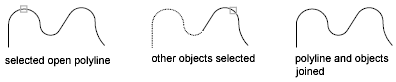
پیوستن
خط ها ، قوس ها یا پلی اتیلن ها را به انتهای یک پلی لاین باز اضافه می کند و منحنی متناسب با منحنی را از یک پلی لاین متناسب با منحنی خارج می کند. برای پیوستن به اشیاء در polyline ، نقاط پایانی آنها باید لمس شوند ، مگر اینکه در اولین پیام PEDIT از گزینه Multiple استفاده کنید. در این حالت ، می توانید به polylines بپیوندید که در صورت عدم فاصله فاز به مقداری بزرگ برای قرار دادن نقاط پایانی ، به آن لمس نکنید.
مشترک
روش پیوستن به polylines انتخاب شده را تنظیم می کند.
- توسعه دادن، گسترش
-
با گسترش یا برش بخشها به نزدیکترین نقاط انتهایی به پلی اتیلن انتخاب شده می پیوندید.
- اضافه کردن
-
با اضافه کردن یک قطعه مستقیم بین نزدیکترین نقاط انتهایی به پلی وین های انتخاب شده می پیوندد.
- هر دو
-
در صورت امکان یا برش در پلی اتیلن انتخاب شده ، در صورت امکان. در غیر این صورت با اضافه کردن یک قطعه مستقیم بین نزدیکترین نقاط انتهایی به پلی وین های انتخاب شده می پیوندد.
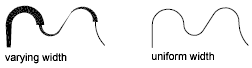
عرض
عرض یکنواخت جدیدی را برای کل پلی لاین مشخص می کند.
می توانید از گزینه Width از گزینه Edit Vertex استفاده کنید تا عرض شروع و پایان یک بخش را تغییر دهید.
Vertex را ویرایش کنید
با کشیدن X بر روی صفحه ، اولین راس پلی لاین را علامت گذاری می کند. اگر جهت مماس را برای این راس مشخص کرده باشید ، یک فلش نیز در آن جهت ترسیم می شود.
بعد
نشانگر X را به راس بعدی منتقل می کند. این نشانگر از انتهای تا شروع پلی الین حتی در صورت بسته بودن پلی لاین پیچیده نمی شود.
قبلی
نشانگر X را به راس قبلی منتقل می کند. نشانگر از ابتدا تا انتهای پلی لاین حتی اگر پلی لاین بسته باشد ، پیچیده نمی شود.
زنگ تفريح
در حالی که نشانگر X را به هر راس دیگر منتقل می کنید ، مکان راس مشخص شده را ذخیره می کند.
اگر یکی از رئوسهای مشخص شده در انتهای پلی لاین باشد ، نتیجه آن یک پلی لاین کوتاه شده است. اگر هر دو راس مشخص شده در انتهای پلی لاین قرار دارند ، یا اگر فقط یک راس مشخص شده باشد و در یک نقطه انتهایی باشد ، نمی توانید از Break استفاده کنید.
- بعد
- قبلی
- برو
-
هر بخش و رئوس را بین دو رئوس که مشخص کرده اید حذف می کند و به حالت ویرایش Vertex باز می گردد.
- خروج
-
Exit Break می شود و به حالت ویرایش Vertex باز می گردد.
درج کنید
یک راس جدید به پلی لاین پس از راس مشخص شده اضافه می کند.

حرکت
راس مشخص شده را حرکت می دهد.
رجن
پلی لاین را بازسازی می کند.

صاف کن
در حالی که نشانگر X را به هر راس دیگر منتقل می کنید ، مکان راس مشخص شده را ذخیره می کند.
اگر می خواهید یک قطعه قوس که دو قطعه مستقیم یک پلی لاین را به هم وصل می کند حذف کرده و سپس بخش های مستقیم را تا زمانی که آنها متصل شوند طولانی کنید ، از دستور FILLET با شعاع فیله 0 استفاده کنید.
- بعد
-
نشانگر X را به راس بعدی منتقل می کند.
- قبلی
-
نشانگر X را به راس قبلی منتقل می کند.
- برو
-
هر بخش و رئوس بین دو راس شما انتخاب می کند حذف می کند ، آنها را با بخش های یک خط مستقیم جایگزین می کند و به حالت ویرایش Vertex باز می گردد. اگر شما فقط یک راس با وارد کردن مشخص بروید بدون حرکت دادن نشانگر ایکس، بخش های زیر است که راس صاف است اگر آن یک قوس است.
- خروج
-
Exit Straighten می شود و به حالت ویرایش Vertex باز می گردد.
مماس
جهت استفاده بعداً در اتصالات منحنی ، جهت مماس را به راس مشخص شده متصل می کنید.
عرض
عرض شروع و پایان را برای بخشی که بلافاصله از راس مشخص شده دنبال می کند تغییر می دهد.
شما باید polyline را بازسازی کنید تا عرض جدید نشان داده شود.
خروج
از حالت ویرایش Vertex خارج می شود.
مناسب
یک پلی لاین متناسب با قوس ایجاد می کند ، یک منحنی صاف تشکیل شده از قوس هایی که به هر جفت از راس ها می پیوندند. منحنی از تمام رئوسهای پلی لاین عبور می کند و از هر جهت مماس که مشخص کرده اید استفاده می کند.
اسپلین
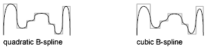
از رئوسهای پلی اتیلن انتخاب شده به عنوان نقاط کنترل یا قاب ، از یک منحنی با تقسیم B- اسپلین استفاده می کند. این منحنی ، به نام پلی لاین متناسب با اسپلین ، از اولین و آخرین نقاط کنترل عبور می کند ، مگر اینکه پلی لاین اصلی بسته شده باشد. منحنی به سمت نقاط دیگر کشیده می شود اما لزوماً از میان آنها عبور نمی کند. هرچه نقاط کنترل بیشتری در قسمت خاصی از قاب مشخص شود ، کشش بیشتری روی منحنی دارند. پلی اتیلن های درجه چهار و مکعب دارای اسپلیت مناسب می توانند تولید شوند.
پلی اتیلن های اسپلیت با منحنی های تولید شده توسط گزینه Fit بسیار متفاوت است. اتصالات جفت قوسهایی را که از هر نقطه کنترل عبور می کنند ، ایجاد می کند. هر دو این منحنی ها با B-splines واقعی تولید شده با دستور SPLINE متفاوت هستند.
اگر پلی لاین اصلی شامل بخش های قوس باشد ، هنگام تشکیل قاب اسپاین صاف می شوند. اگر قاب دارای عرض باشد ، نوارهای اسپلینگ حاصل از هموار از عرض اولین راس تا عرض آخرین راس را صاف کنید. تمام اطلاعات عرض متوسط نادیده گرفته می شود. پس از اسپل شدن ، قاب ، در صورت نمایش ، با عرض صفر و پیوستگی مداوم نشان داده می شود. مشخصات مماس بر روی نقاط کنترل هیچ تاثیری در اتصالات اسپلی ندارد.
هنگامی که یک منحنی متناسب با اسپلین در یک پلی لاین مناسب باشد ، قاب منحنی متناسب با اسپلین ذخیره می شود به طوری که می توان آن را با یک فروپاشی بعدی فراخواند. با استفاده از گزینه PEDIT Decurve می توانید منحنی متناسب با اسپلین را به داخل قاب آن بپیچانید. این گزینه بر روی منحنی های مناسب به همان روشی که در splines انجام می شود کار می کند.
بیشتر دستورات ویرایش هنگامی که برای پلی اتیلن های اسپلینگ یا منحنی های مناسب اعمال می شوند ، یکسان عمل می کنند.
- MOVE ، ERASE ، COPY ، MIRROR ، ROTATE و SCALE بر روی منحنی اسپلین و قاب آن کار می کنند ، چه فریم قابل مشاهده باشد یا نه.
- EXTEND با اضافه کردن یک راس جدید ، قاب را تغییر می دهد که در آن خط اولیه یا نهایی قاب ، هندسه مرزی را با هم تلاشی می کند.
- BREAK و TRIM یک پلی لاین را تولید می کنند که فقط دارای خط خم شده است ، که مطابق با منحنی های مناسب است ، جایی که محل انحنای منحنی دائمی است.
- EXPLODE فریم را پاک می کند و خطوط و قوس هایی برای تقریب پلی لاین متناسب با اسپلین ایجاد می کند.
- OFFSET با استفاده از منحنی های متناسب ، رفتار خود را با خط خمیده مناسب تولید می کند.
- DIVIDE ، MASURE ، و گزینه Object AREA و HATCH فقط فریم مناسب را می بینید ، نه فریم.
- STRETCH پس از کشش ، اسپلین را به قاب کشیده بازگرداند.
گزینه Join PEDIT اسپلین را خراب می کند و اطلاعات spline اصلی و سایر پلی اتیل های اضافه شده را دور می زند. پس از اتمام عملیات پیوستگی ، می توانید یک ستون جدید را در پلی لاین حاصل بدست آورید.
گزینه های ویرایش ورتکس PEDIT اثر زیر را دارند:
- گزینه های بعدی و قبلی نشانگر X را فقط به نقاط روی قاب اسپل اعم از قابل مشاهده یا غیر منتقل می کند.
- گزینه Break spline را دور می کند.
- گزینه های Insert ، Move ، Straighten و Width بطور خودکار اسپلین را تغییر می دهد.
- گزینه Tangent هیچ تاثیری روی splines ندارد.
ضربه محکم و ناگهانی Object فقط از منحنی متناسب اسپلین استفاده می کند ، نه از قاب. اگر می خواهید به نقاط کنترل قاب بروید ، از PEDIT استفاده کنید تا ابتدا قاب پلی لاین را به یاد بیاورید.
متغیر سیستم SPLINETYPE نوع منحنی اسپلین تقریبی را کنترل می کند. با تنظیم SPLINETYPE به 5 ، یک خط B- اسپلیت درجه یک تقریب می شود. تنظیم SPLINETYPE بر روی 6 تقسیم خط B- اسپلیت مکعب است.
می توانید ظرافت یا درشت بودن تقریب اسپلین را با متغیر سیستم SPLINESEGS بررسی یا تغییر دهید. مقدار پیش فرض 8 است. اگر مقدار را بالاتر قرار دهید ، تعداد بیشتری از بخش های خط ترسیم می شوند و تقریب به spline ایده آل دقیق تر می شود. spline تولید شده فضای بیشتری را در پرونده ترسیم اشغال می کند و مدت زمان بیشتری برای تولید آن طول می کشد.
اگر SPLINESEGS را روی یک مقدار منفی تنظیم کنید ، این برنامه بخش هایی را با استفاده از مقدار مطلق تنظیمات تولید می کند و سپس یک منحنی متناسب با آن بخش ها اعمال می کند. منحنی های متناسب از قوس ها به عنوان بخش های تقریبی استفاده می کنند. با استفاده از قوس ها ، در صورت مشخص شدن بخش های مختلف ، منحنی نرم تر تولید می شود ، اما منحنی می تواند مدت بیشتری طول بکشد.

برای تغییر تعداد بخش های مورد استفاده برای قرار دادن یک طناب موجود ، SPLINESEGS را تغییر داده و منحنی را خط بزنید. لازم نیست ابتدا آنرا تجزیه کنید.
کمرنگ شدن
راسهای اضافی که توسط یک منحنی متناسب یا اسپلین وارد شده اند را حذف می کند و تمام بخش های پلی لاین را صاف می کند. اطلاعات مماس را برای استفاده در درخواست های منحنی مناسب متعاقب به vertices polyline اختصاص داده می کند. اگر یک polyline متناسب با spline را با دستوری مانند BREAK یا TRIM ویرایش می کنید ، نمی توانید از گزینه Decurve استفاده کنید.
ژنرال Ltype
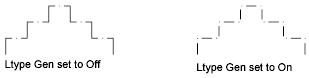
لاینتایپ را در یک الگوی مداوم از طریق راسهای پلی لاین تولید می کند. با خاموش بودن ، این گزینه خط شروع و پایان دادن به خط تیره را در هر راس ایجاد می کند. Ltype Gen در مورد پلی اتیلن با بخش های مخروط صدق نمی کند.
معکوس
ترتیب رأس پلی لاین را برعکس می کند. با استفاده از این گزینه جهت معکوس جهت اشیاء استفاده شده از linetypes با متن شامل. به عنوان مثال ، بسته به جهتی که در آن یک پلی لاین ایجاد شده است ، متن موجود در لباس زیر ممکن است به صورت وارونه نمایش داده شود.
واگرد
عملیات را تا آغاز جلسه PEDIT معکوس می کند.
2D Polyline Selection (PEDIT)
Selecting a 2D polyline provides specialized PEDIT options.
You can select a single arc or line segment, also called a subobject, within a polyline by pressing the Ctrl key when you click over it (not available in AutoCAD LT).
If the polyline you select is a closed polyline, Open replaces the Close option in the prompt. You can edit a 2D polyline if its normal is parallel to and in the same direction as the Z axis of the current UCS.
The following prompts are displayed.
Close
Creates the closing segment of the polyline, connecting the last segment with the first. The polyline is considered open unless you close it using the Close option.
Open
Removes the closing segment of the polyline. The polyline is considered closed unless you open it using the Open option.
Join
Adds lines, arcs, or polylines to the end of an open polyline and removes the curve fitting from a curve-fit polyline. For objects to join the polyline, their endpoints must touch unless you use the Multiple option at the first PEDIT prompt. In this case, you can join polylines that do not touch if the fuzz distance is set to a value large enough to include the endpoints.
Jointype
Sets the method of joining selected polylines.
- Extend
-
Joins the selected polylines by extending or trimming the segments to the nearest endpoints.
- Add
-
Joins the selected polylines by adding a straight segment between the nearest endpoints.
- Both
-
Joins the selected polylines by extending or trimming if possible. Otherwise joins the selected polylines by adding a straight segment between the nearest endpoints.
Width
Specifies a new uniform width for the entire polyline.
You can use the Width option of the Edit Vertex option to change the starting and ending widths of a segment.
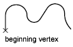
Edit Vertex
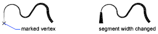
Marks the first vertex of the polyline by drawing an X on the screen. If you have specified a tangent direction for this vertex, an arrow is also drawn in that direction.
Next
Moves the X marker to the next vertex. The marker does not wrap around from the end to the start of the polyline even if the polyline is closed.
Previous
Moves the X marker to the previous vertex. The marker does not wrap around from the start to the end of the polyline even if the polyline is closed.
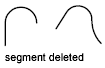
Break
Saves the location of the marked vertex while you move the X marker to any other vertex.
If one of the specified vertices is at an end of the polyline, the result is one truncated polyline. If both specified vertices are at endpoints of the polyline, or if just one vertex is specified and it is at an endpoint, you cannot use Break.
- Next
- Previous
- Go
-
Deletes any segments and vertices between the two vertices you specify and returns to Edit Vertex mode.
- Exit
-
Exits Break and returns to Edit Vertex mode.
Insert
Adds a new vertex to the polyline after the marked vertex.
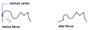
Move
Moves the marked vertex.
Regen
Regenerates the polyline.
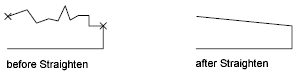
Straighten
Saves the location of the marked vertex while you move the X marker to any other vertex.
If you want to remove an arc segment that connects two straight segments of a polyline and then extend the straight segments until they intersect, use the FILLET command with a fillet radius of 0.
- Next
-
Moves the X marker to the next vertex.
- Previous
-
Moves the X marker to the previous vertex.
- Go
-
Deletes any segments and vertices between the two vertices you select, replaces them with single straight line segments, and returns to Edit Vertex mode. If you specify only one vertex by entering go without moving the X marker, the segment following that vertex is straightened if it is an arc.
- Exit
-
Exits Straighten and returns to Edit Vertex mode.
Tangent
Attaches a tangent direction to the marked vertex for use later in curve fitting.
Width
Changes the starting and ending widths for the segment that immediately follows the marked vertex.
You must regenerate the polyline to display the new width.
Exit
Exits Edit Vertex mode.
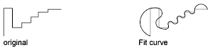
Fit
Creates an arc-fit polyline, a smooth curve consisting of arcs joining each pair of vertices. The curve passes through all vertices of the polyline and uses any tangent direction you specify.
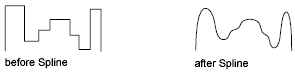
Spline
Uses the vertices of the selected polyline as the control points, or frame, of a curve approximating a B-spline. This curve, called a spline-fit polyline, passes through the first and last control points unless the original polyline was closed. The curve is pulled toward the other points but does not necessarily pass through them. The more control points you specify in a particular part of the frame, the more pull they exert on the curve. Quadratic and cubic spline-fit polylines can be generated.
Spline-fit polylines are very different from the curves produced by the Fit option. Fit constructs pairs of arcs that pass through every control point. Both of these curves are different from true B-splines produced with the SPLINE command.
If the original polyline included arc segments, they are straightened when the spline’s frame is formed. If the frame has width, the resulting spline tapers smoothly from the width of the first vertex to the width of the last vertex. All intermediate width information is ignored. Once spline-fit, the frame, if displayed, is shown with zero width and CONTINUOUS linetype. Tangent specifications on control point vertices have no effect on spline-fitting.
When a spline-fit curve is fit to a polyline, the spline-fit curve’s frame is stored so that it can be recalled by a subsequent decurving. You can turn a spline-fit curve back into its frame polyline by using the PEDIT Decurve option. This option works on fit curves in the same manner as it does on splines.
Most editing commands act the same when applied to spline-fit polylines or fit curves.
- MOVE, ERASE, COPY, MIRROR, ROTATE, and SCALE operate on both the spline curve and its frame, whether the frame is visible or not.
- EXTEND changes the frame by adding a new vertex where the initial or final line of the frame intersects the boundary geometry.
- BREAK and TRIM generate a polyline with only the fit spline, which is consistent with fit curves, where the curve fitting is permanent.
- EXPLODE deletes the frame and generates lines and arcs to approximate the spline-fit polyline.
- OFFSET generates a polyline with only the fit spline, which is consistent with its behavior with fit curves.
- DIVIDE, MEASURE, and the Object option of AREA and HATCH see only the fit spline, not the frame.
- STRETCH refits the spline to the stretched frame after a spline is stretched.
The Join option of PEDIT decurves the spline and discards the spline information of the original and any added polylines. Once the Join operation is complete, you can fit a new spline to the resulting polyline.
The Edit Vertex options of PEDIT have the following effect:
- The Next and Previous options move the X marker only to points on the frame of the spline, whether visible or not.
- The Break option discards the spline.
- The Insert, Move, Straighten, and Width options automatically refit the spline.
- The Tangent option has no effect on splines.
Object snap uses only the spline-fit curve itself, not the frame. If you want to snap to the frame control points, use PEDIT to recall the polyline frame first.
The SPLINETYPE system variable controls the type of spline curve approximated. Setting SPLINETYPE to 5 approximates a quadratic B-spline. Setting SPLINETYPE to 6 approximates a cubic B-spline.
You can examine or change the fineness or coarseness of the spline approximation with the SPLINESEGS system variable. The default value is 8. If you set the value higher, a greater number of line segments are drawn and the approximation to the ideal spline becomes more precise. The generated spline occupies more space in the drawing file and takes longer to generate.
If you set SPLINESEGS to a negative value, the program generates segments using the absolute value of the setting and then applies a fit-type curve to those segments. Fit-type curves use arcs as the approximating segments. Using arcs yields a smoother generated curve when few segments are specified, but the curve can take longer to generate.
To change the number of segments used to fit an existing spline, change SPLINESEGS and respline the curve. You do not have to decurve it first.
Decurve
Removes extra vertices inserted by a fit or spline curve and straightens all segments of the polyline. Retains tangent information assigned to the polyline vertices for use in subsequent fit curve requests. If you edit a spline-fit polyline with a command such as BREAK or TRIM, you cannot use the Decurve option.
Ltype Gen
Generates the linetype in a continuous pattern through the vertices of the polyline. When turned off, this option generates the linetype starting and ending with a dash at each vertex. Ltype Gen does not apply to polylines with tapered segments.
Reverse
Reverses the order of vertices of the polyline. Use this option to reverse the direction of objects that use linetypes with included text. For example, depending on the direction in which a polyline was created, the text in the linetype might be displayed upside down.
Undo
Reverses operations as far back as the beginning of the PEDIT session.