نمای جزئی از قسمتی از نمای نقشه مدل را ایجاد می کند.
برگه طرح بندی  ایجاد جزئیات پانل مشخصات
روی نمای والدین راست کلیک کرده و گزینه View View Detail View را انتخاب کنید
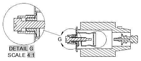
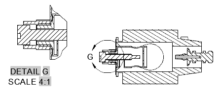
نمای جزئیات ، نمای نقاشی است که شامل بخشی از نمای نقشه دیگر است و در مقیاس بزرگتر بزرگنمایی می شود. می توانید یک نمای جزئیات دایره ای یا مستطیلی داشته باشید. این دستور فقط در طرح پشتیبانی می شود و شما باید یک نقاشی داشته باشید.
با اجرای این دستور پیام های زیر نمایش داده می شود.
منظره ای را نشان می دهد که از آن می توان نمای جزئیات را استخراج کرد.
نقطه مرجع والدین را برای مرز نمایش جزئیات مشخص می کند.
این پانل فقط زمانی قابل مشاهده است که شما یک نمای جزئیات از یک مدل Inventor ایجاد کرده اید. هنگام ایجاد نمای جزئیات ، فقط می توانید مقادیر مربوط به Design View را ویرایش کنید.
گزینه های نمایش را برای نمای جزئیات مشخص می کند.
مقیاس نمای جزئیات را مشخص می کند. به طور پیش فرض ، مقیاس نمای جزئیات دو برابر از والدین یا مقدار بزرگتر بعدی در لیست مقیاس در پانل Appearance
روی روبان است.
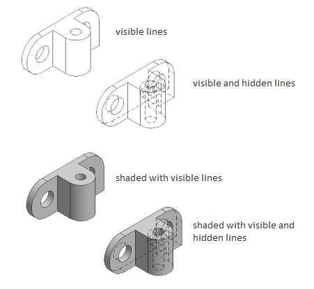
گزینه های دید را برای تنظیم جزئیات نمای مشخص می کند. گزینه های قابلیت مشاهده شیء مدل خاص هستند و ممکن است برخی از گزینه ها در مدل انتخابی و از نظر ایجاد مدل وجود نداشته باشد.
لبه های تداخل را روشن یا خاموش می کند. هنگام روشن بودن ، این نمایشگر ، هر دو لبه پنهان و قابل رویت را نمایش می دهد که در غیر این صورت به دلیل شرایط تداخل از مطالعه حذف شده اند.
لبه های مماس را روشن یا خاموش می کند. هنگامی که روشن است ، نمای خطی را نشان می دهد تا تقاطع سطوح ملاقات را بصورت مماس نشان دهد.
خطوط میزان خم ورق فلز را روشن یا خاموش می کند. خطوط اندازه خم فلزی نشانگر موقعیت گذار که در آن یک خم لولا یا چین خورده است ، در یک
نمای فلز مسطح شده است. این گزینه فقط در صورتی موجود است که مدل مربوطه دارای یک صفحه فلزی مسطح باشد که در آن مشخص شده است.
قابلیت دید خطوط نخ را در پیچ ها و سوراخ های ضبط شده را روشن یا خاموش می کند.
قابلیت مشاهده مسیرهای ارائه را روشن یا خاموش می کند. مسیرهای ارائه خطوط در نمای منفجر شده (در یک فایل ارائه) هستند که مسیری را نشان می دهند که در طی آن اجزاء به موقعیت مونتاژ منتقل می شوند.
نوع مرزی نمای جزئیات را مشخص می کند.
برچسب مرز جزئیات و نمای جزئیات نتیجه را مشخص می کند.برنامه همیشه از طراحی ، برچسب جزئیات بعدی رایگان تعیین می کند.
مشخص می کند که متن برچسب نمایش جزئیات نمایش داده شده است یا نه.
مشخص می کند که خط برش در مدل در نمای جزئیات صاف است.
برچسب مرز جزئیات و نمای جزئیات نتیجه را مشخص می کند.
مشخص می کند که متن برچسب نمایش جزئیات نمایش داده شده است یا خیر.
بعد از قرار گرفتن در قسمت نقشه ، بدون اینکه مجبور شوید از دستور خارج شوید ، نمای جزئیات را جابجا می کند.
به قسمت قبلی باز می گردد ، یا بسته به مکانی که در چرخه فرمان باشد گزینه ظاهر می شود ، فرمان را تکمیل می کند.
Creates a detail view of a portion of a model documentation drawing view.
Layout tab Create View panel Detail
Right-click a parent view and choose Create View Detail View
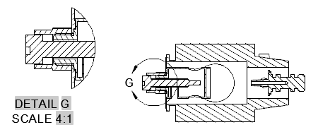
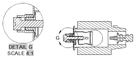
A detail view is a drawing view that contains a portion of another drawing view and
is magnified to a larger scale. You can have a circular or rectangular detail view.
This command is only supported in the layout and you must have a drawing view.
The following prompts are displayed.
Specifies a view from which to derive the detail view.
Specifies the center point on the parent for the detail view boundary.
This panel is visible only when you have created a detail view from an Inventor model.
When creating detail views, you can only edit the values for Design View.
Specifies the display options for the detail view.
Specifies the scale of the detail view. By default, the scale of detail view is twice
of the parent view or the next larger value in the Scale list on the Appearance panel
on the ribbon.
Specifies the visibility options to set for the detail view. Object visibility options
are model specific and some options may not be available in the selected model, and
in the view created of the model.
Turns visibility of interference edges on or off. When turned on, the view displays
both hidden and visible edges that are otherwise excluded due to an interference condition.
Turns visibility of tangent edges on or off. When turned on, the view displays a line
to show the intersection of surfaces meeting tangentially.
Turns visibility of sheet metal bend extent lines on or off. Sheet metal bend extent
lines indicate the location of transition about which a bend hinges or folds, in a
flattened sheet metal view.
This option is available only if the corresponding model has a flattened sheet metal
view defined in it.
Turns visibility of thread lines on screws and tapped holes on or off.
Turns visibility of presentation trails on or off. Presentation trails are lines in
an exploded view (in a presentation file) that show the direction along which a components
are moved into assembled position.
Specifies the detail view boundary type.
Specifies that a rectangular boundary is used to create the detail view.
If Infer Constraint is on, the corner of the rectangular detail boundary is associated
to a point on the parent view. If Infer Constraint is off, the corner of the rectangular
detail boundary will not be associated to a point on the parent view.
Specifies the label for the detail boundary and the resulting detail view.
The program always determines from the drawing, the next free detail label.
Specifies if the detail view label text is displayed or not.
Specifies that the cutout line on the model within the detail view is smooth.
Specifies that the cutout line on the model within the detail view is jagged.
There is no border for the detail view and no leader line between the detail view
and the detail boundary in the parent view.
Specifies the label for the detail boundary and the resulting detail view.
Specifies if the detail view label text is displayed.
Moves the detail view, after it is placed in the drawing area, without forcing you
exit the command.
Goes back to the previous prompt, or completes the command, depending on where in
the command cycle the option appears.