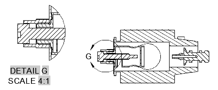
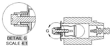
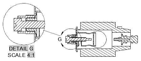
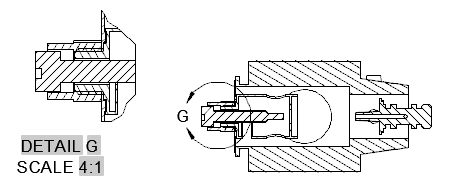
Creates a detailed view of a portion of an existing model documentation drawing view.
The following options are displayed.
This panel is visible only when you create a base view from an Inventor model. This
panel is visible only when you are editing a detail view created from an Inventor
model. The options you can view and edit depend on the properties of the selected
model. In the editor mode, you can only edit the values for Design View.
Specifies the display style to use for the selected detail view.
Specifies the scale to use for the detail view. You can select a standard scale from
the drop-down list, or directly enter a non-standard scale.
Displays a list of objects to show in the detail view.
This option is disabled when creating a detail view.
Displays the View Options dialog box. This dialog box specifies how to anchor the
detail view being created, and how to display Inventor Reference Parts.
Specifies that a circular boundary is used to create the detail view. This is the
default boundary type.
If Infer Constraint is on, the center of the circular detail boundary is associated
to a point on the parent view. If Infer Constraint is off, the center of the circular
detail boundary is not associated to a point on the parent view.
If Infer Constraint is on, the corner of the rectangular detail boundary is associated
to a point on the parent view. If Infer Constraint is off, the corner of the rectangular
detail boundary will not be associated to a point on the parent view.
There is no border for the detail view and no connection line between the detail view
and the detail boundary in the parent view.
Specifies the label for the detail boundary and the resulting detail view.
Specifies if the detail view label text is displayed.
eates a detailed view of a portion of an existing model documentation drawing view. List of Options The following options are displayed. Representation Panel …detail view created from an … Saves the changes and exits the Detail View Creation ribbon contextual tab.View Creation Ribbon Contextual Tab … AutoCAD P&ID 2016, AutoCAD Plant 3D 2016, AutoCAD Structural Detailing ۲۰۱۶, & AutoCAD Utility Design …View Creation Ribbon Contextual Tab … AutoCAD Mechanical 2016, AutoCAD P&ID 2016, AutoCAD Plant 3D 2016, AutoCAD Structural Detailing ۲۰۱۶, …Detailing … Specifies if the view created out of a section view inherits the section cut. … Exits the Section View Creation ribbon contextual tab without saving the changes.Detail View with a Rectangular Boundary Click Layout tab > Create View panel … these settings using the Detail View Creation Ribbon Contextual Tab.detail representation to show in the selected view. … Saves changes and closes the Drawing View Creation Ribbon Contextual Tab.Detail View Creation Ribbon Contextual Tab. For example, you can specify the detail view identifier, …Detail View Creation Ribbon Contextual Tab. For example, you can specify the detail view identifier, scale and visibility …