با برش یا تقسیم اشیاء موجود ، مواد جامد و سطحی جدید ۳D ایجاد می کند.
هواپیمای برش با مشخص کردن یک صفحه اصلی از UCS یا با انتخاب یک مسطح یا یک سطح سطح (اما مش نیست) با ۲ یا ۳ نقطه تعریف می شود . یک یا هر دو طرف اشیاء خرد شده را می توان حفظ کرد.
- اشیاء جامد سه بعدی را می توان با استفاده از هواپیماها و اشیاء سطح مشخص شده خرد کرد
- اشیاء سطح فقط توسط هواپیماهای مشخص شده قابل برش هستند
- مش نمی تواند به صورت مستقیم برش داده شود یا از آن به عنوان سطوح برش استفاده شود
اشیاء برش یافته لایه و رنگی اشیاء اصلی را حفظ می کنند ، اما اشیاء جامد یا سطحی حاصل سابقه ای از اشیاء اصلی را حفظ نمی کنند.
با اجرای دستور پیام های زیر نمایش داده می شود.
- اشیاء برش
-
شیء جامد یا سطحی سه بعدی را که می خواهید برش دهید مشخص می کند. اگر یک شی مش را انتخاب کنید ، می توانید قبل از انجام
عملیات برش ، آن را به یک جامد سه بعدی یا سطح تبدیل کنید .
- نقطه شروع هواپیما برش
- مسطح
- سطح
- محور Z
- چشم انداز
- XY
- YZ
- XZ
- ۳ امتیاز
- نقطه شروع هواپیما برش
-
اولین دو نقطه را تعیین می کند که جهت یابی هواپیمای برش را تعیین می کند. با این گزینه ، هواپیمای برش همیشه عمود بر هواپیمای XY UCS فعلی است. بعد از اینکه نکته دوم را در هواپیما مشخص کردید ، می توانید انتخاب کنید که آیا هر دو طرف شیء خرد شده را نگه دارید یا می توانید
نقطه دیگری را در کنار هواپیما که می خواهید نگه دارید مشخص کنید.
- نکته دوم در هواپیما. دوم از دو نقطه را در صفحه برش تنظیم می کند. اگر نکته دوم در هواپیمای XY UCS واقع نشود ، بر روی هواپیما پیش بینی می شود.
- برای نگه داشتن ، یک نقطه را در طرف مورد نظر مشخص کنید
- هر دو طرف را نگه دارید
- مسطح
-
صفحه برش را با هواپیما که حاوی دایره انتخابی ، بیضوی ، قوس دایره ای یا بیضوی ، اسپلین ۲D ، پلی لاین ۲D یا پلی لاین سه بعدی مسطح باشد ، تراز می کند .
- یک دایره ، بیضی ، قوس ، ۲D-spline یا ۲D-polyline را انتخاب کنید. شیء مسطح را مشخص می کند که صفحه برش را مشخص می کند. همچنین می توان یک شیء چند خطی مسطح ۳D نیز انتخاب کرد.
- برای نگه داشتن ، یک نقطه را در طرف مورد نظر مشخص کنید
- هر دو طرف را نگه دارید
- سطح
-
صفحه برش را با یک سطح انتخاب شده تراز می کند.
- یک سطح را انتخاب کنید. سطح برش را مشخص می کند.
توجه: شما نمی توانید مش ، صورت سه بعدی یا اشیاء ضخیم را به عنوان سطح برش مشخص کنید.
- برای نگه داشتن ، شیء برش خورده را در طرف مورد نظر خود انتخاب کنید
- هر دو طرف را نگه دارید
- محور Z
-
تعریف می کند هواپیما برش بوسیله تعیین یک نقطه بر روی هواپیما و نقطه دیگر در Z محور (نرمال) از هواپیما.
- نقطه ای از صفحه را مشخص کنید. نقطه ای را در صفحه قطعه قطعه تنظیم می کند.
- نقطه ای را در محور Z (عادی) هواپیما مشخص کنید. نقطه ای را مشخص می کند که محور عمود بر صفحه برش را مشخص می کند.
- برای نگه داشتن ، یک نقطه را در طرف مورد نظر مشخص کنید
- هر دو طرف را نگه دارید
- چشم انداز
-
صفحه برش را به موازات صفحه مشاهده منظر فعلی تراز می کند. با مشخص کردن یک نقطه موقعیت هواپیمای برش را مشخص می کند.
- نقطه ای را در صفحه نمای فعلی مشخص کنید. برای شروع برش ، یک نقطه را بر روی جسم تنظیم می کند.
- برای نگه داشتن ، یک نقطه را در طرف مورد نظر مشخص کنید
- هر دو طرف را نگه دارید
- XY
-
هواپیمای برش را با هواپیمای XY UCS فعلی تراز می کند . یک نقطه را برای تعیین محل هواپیمای برش مشخص کنید.
- روی هواپیمای XY قرار بگیرید. صفحه برش را به موازات هواپیمای XY UCS تراز می کند و از یک نقطه مشخص عبور می کند.
- برای نگه داشتن ، یک نقطه را در طرف مورد نظر مشخص کنید
- هر دو طرف را نگه دارید
- YZ
-
هواپیمای برش را با هواپیمای XY UCS فعلی تراز می کند . یک نقطه را برای تعیین محل هواپیمای برش مشخص کنید.
- هواپیما YZ را نشان دهید. هواپیمای برش را به موازات هواپیمای YZ UCS تراز می کند و از یک نقطه مشخص عبور می کند.
- برای نگه داشتن ، یک نقطه را در طرف مورد نظر مشخص کنید
- هر دو طرف را نگه دارید
- XZ
-
هواپیمای برش را با هواپیمای XZ UCS فعلی تراز می کند . یک نقطه را برای تعیین محل هواپیمای برش مشخص کنید.
- روی هواپیمای XZ قرار بگیرید. صفحه برش را به موازات هواپیمای XZ UCS تراز می کند و از یک نقطه مشخص عبور می کند.
- برای نگه داشتن ، یک نقطه را در طرف مورد نظر مشخص کنید
- هر دو طرف را نگه دارید
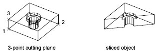
- ۳ امتیاز
-
هواپیمای برش را با استفاده از سه نقطه تعریف می کند.
- برای نگه داشتن ، یک نقطه را در طرف مورد نظر مشخص کنید
-
از یک نقطه برای تعیین اینکه کدام سمت از شیء برش خورده برای حفظ استفاده می کند استفاده می کند. نکته نمی تواند در هواپیما برش باشد.
- هر دو طرف را نگه دارید
-
هر دو طرف اشیاء خرد شده را حفظ می کند.
SLICE (Command)
Creates new 3D solids and surfaces by slicing, or dividing, existing objects.
The cutting plane is defined with 2 or 3 points by specifying a major plane of the
UCS, or by selecting a planar or a surface object (but not a mesh). One or both sides
of the sliced objects can be retained.
- ۳D solid objects can be sliced using specified planes and surface objects
- Surface objects can be sliced by specified planes only
- Meshes cannot directly be sliced or used as slicing surfaces
Sliced objects retain the layer and color properties of the original objects, however
the resulting solid or surface objects do not retain a history of the original objects.
The following prompts are displayed.
- Objects to slice
-
Specifies the 3D solid or surface object that you want to slice. If you select a mesh
object, you can choose to convert it to a 3D solid or surface before completing the
slice operation.
- Start point of slicing plane
- Planar object
- Surface
- Z axis
- View
- XY
- YZ
- XZ
- ۳points
- Start point of slicing plane
-
Sets the first of two points that define the orientation of the slicing plane. With
this option, the slicing plane is always perpendicular to the XY plane of the current UCS. After you specify the second point on the plane, you can
choose whether to keep both sides of the sliced object or you can specify another
point on the side of the plane that you want to keep.
- Second point on plane. Sets the second of two points on the slicing plane. If the second point is not located
on the XY plane of the UCS, it is projected onto the plane.
- Specify a point on the desired side to keep
- Keep both sides
- Planar object
-
Aligns the cutting plane with a plane that contains the selected circle, ellipse,
circular or elliptical arc, 2D spline, 2D polyline, or planar 3D polyline.
- Select a circle, ellipse, arc, 2D-spline, or 2D-polyline. Specifies the planar object that defines the cutting plane. A planar 3D polyline
object can also be selected.
- Specify a point on desired side to keep
- Keep both sides
- Surface
-
Aligns the cutting plane with a selected surface.
- Select a surface. Specifies a cutting surface.
NOTE:You cannot specify mesh, 3D face, or thickened objects as the cutting surface.
- Select the sliced object on the desired side to keep
- Keep both sides
- Z axis
-
Defines the cutting plane by specifying a point on the plane and another point on
the Z axis (normal) of the plane.
- Specify a point on the section plane. Sets a point on the slicing plane.
- Specify a point on the Z-axis (normal) of the plane. Specifies a point that defines the axis that is perpendicular to the slicing plane.
- Specify a point on the desired side to keep
- Keep both sides
- View
-
Aligns the cutting plane parallel to the current viewport’s viewing plane. Specifying
a point defines the location of the cutting plane.
- Specify a point on the current view plane. Sets a point on the object to start the slice.
- Specify a point on the desired side to keep
- Keep both sides
- XY
-
Aligns the cutting plane with the XY plane of the current UCS. Specify a point to define the location of the cutting plane.
- Point on the XY-plane. Aligns the cutting plane parallel to the XY plane of the UCS and passing through a specified point.
- Specify a point on the desired side to keep
- Keep both sides
- YZ
-
Aligns the cutting plane with the XY plane of the current UCS. Specify a point to define the location of the cutting plane.
- Point on the YZ-plane. Aligns the cutting plane parallel to the YZ plane of the UCS and passing through a specified point.
- Specify a point on the desired side to keep
- Keep both sides
- XZ
-
Aligns the cutting plane with the XZ plane of the current UCS. Specify a point to define the location of the cutting plane.
- Point on the XZ-plane. Aligns the cutting plane parallel to the XZ plane of the UCS and passing through a specified point.
- Specify a point on the desired side to keep
- Keep both sides
- ۳points
-
Defines the cutting plane using three points.
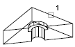
- Specify a point on the desired side to keep
-
Uses a point to determine which side of the sliced object to keep. The point cannot
lie on the cutting plane.
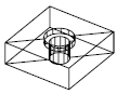
- Keep both sides
-
Retains both sides of the sliced objects.