Perform editing operations such as erase, move, and trim on the objects in a drawing.
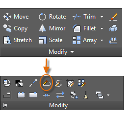
The most common of these tools are located on the Modify panel of the Home tab. Take
a minute to look through them.
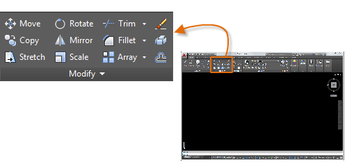
To erase an object, use the ERASE command. You can enter E in the Command window,
or click the Erase tool. When you see the cursor change to a square pickbox, click each object that you want to erase, and then press Enter or the Spacebar.
Sometimes you need to select a large number of objects. Instead of selecting each
object individually, you can select the objects in an area by clicking an empty location
(۱), moving your cursor right or left, and then clicking a second time (2).
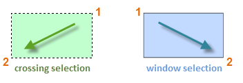
The result is called the selection set, the set of objects that will be processed by a command.
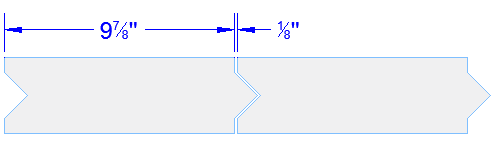
Here’s how you would use the COPY command to lay out a row of decorative tiles. Starting
with a polyline that represents its shape, you need to make copies that are 1/8″ apart.
You click the Copy tool or enter CP in the Command window to start the command. From
here, you can choose between two primary methods, depending on what’s more convenient.
You will use these two methods frequently.
In this case, you know that any point on the second tile will be a total of 9-7/8″
+ ۱/۸″ = ۱۰″ from the equivalent point on the original tile. So, you select the tile,
press Enter or the Spacebar to end your selection, and click anywhere in the drawing
area (1). This point does not have to be located on the tile.
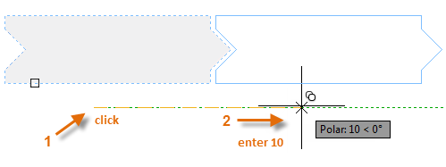
Next, you move your cursor to the right, relying on the polar tracking angle to keep
the direction horizontal, and then enter 10 for the distance. Press Enter or the Spacebar
a second time to end the command.
When you specified a distance and a direction from a point (1), you defined a vector.
This vector was applied to the tile that you selected.
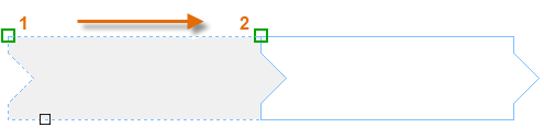
Another method, one that you will often use when you don’t want to add numbers together,
requires two steps. You start the COPY command and select the tile as before, but
this time you click the two endpoints as shown. This also defines a vector.
Next, to add the 1/8″ space between the tiles, click the Move tool or enter M in the
Command window. The MOVE command is similar to the COPY command. Select the newly
copied tile, and press Enter or the Spacebar. As before, click anywhere in the drawing
area and move your cursor to the right. Enter 1/8 or .125 for the distance.
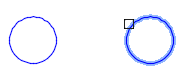
You can use the two-points method as a repeating sequence. Let’s say that you want
to make more copies of the circle at the same horizontal distance. You start the COPY
command and select the circle as shown.
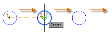
Then, using the Center object snap, click the center of circle 1, followed by the
center of circle 2, and so on.
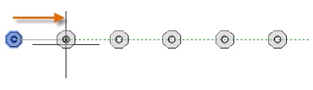
For larger numbers of copies, try experimenting with the Array option of the COPY
command. For example, here’s a linear arrangement of deep foundation piles. From a
base point, you specify number of copies and the center-to-center distance.
Most models include a lot of parallel lines and curves. Creating them is easy and
efficient with the OFFSET command. Click the OFFSET tool or enter O in the Command
window.

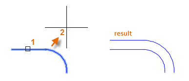
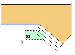
Select the object (1), specify the offset distance, and click to indicate on which
side of the original that you want the result (2). Here is an example of offsetting
a polyline.
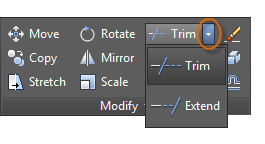
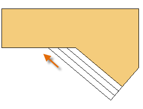
A popular technique is to use the OFFSET command in combination with the TRIM and
EXTEND commands. In the Command window, you can enter TR for TRIM or EX for EXTEND.
Trimming and extending are some of the most commonly used operations.
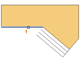
In the following illustration, you want to extend the lines that represent the steps
for this deck. You start the Extend command, select the boundary, and then press Enter
or the Spacebar.
Pressing Enter or the Spacebar indicates that you’ve finished selecting the boundaries,
and that you’re now ready to select the objects to be extended.
Next, you select the objects to be extended (near the ends to be extended), and then
you press Enter or the Spacebar to end the command.
The result is that the lines are extended to the boundary.
The TRIM command follows the same steps, except that when you select the objects to
trim, you select the portions to trim away.
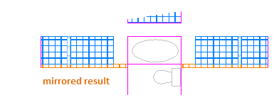
The following illustration comes from a tile project. The walls in this residential
bathroom are flattened out to be able to lay out the tile pattern and estimate the
number of tiles needed.
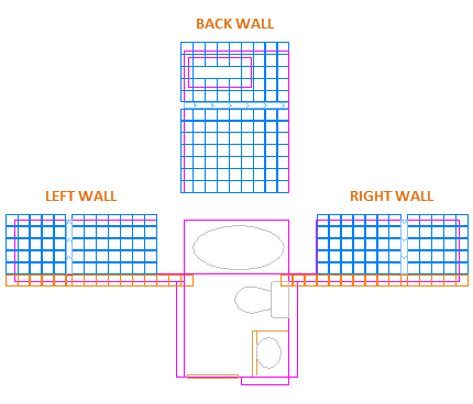
You can save a lot of work by taking advantage of the symmetry between the left and
right walls. All you need to do is create the tiles on one wall and then mirror the
wall across the center of the room.
In the example below, you start the MIRROR command (or enter MI in the Command window),
use window selection (1 and 2) to select the geometry on the right wall, and then
specify a mirror line (3 and 4) corresponding to the centerline of the bathroom.
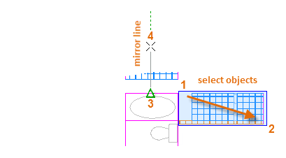
Finally, decline the option to “Erase source objects” by pressing Enter or the Spacebar.
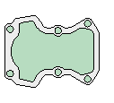
You can stretch most geometric objects. This lets you lengthen and shorten parts of
your model. For example, this model might be a gasket or the design for a public park.
Use the STRETCH command (or enter S in the Command window) and select the objects
with a crossing selection as shown below (1 and 2). The crossing selection is mandatory—only
the geometry that is crossed by the crossing selection is stretched. Then click anywhere
in the drawing area (3), move the cursor to the right, and enter 50 as the distance.
This distance might represent millimeters or feet.
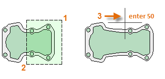
To shorten the model by a specified amount, you’d move your cursor to the left instead.
The FILLET command (enter F in the Command window) creates a rounded corner by creating
an arc that is tangent to two selected objects. Notice that the fillet is created
relative to where you select the objects.
You can create a fillet between most types of geometric objects, including lines,
arcs, and polyline segments.
The EXPLODE command (enter X in the Command window) disassociates a compound object
into its component parts. You can explode objects such as polylines, hatches, and
blocks (symbols).
After you explode a compound object, you can modify each resulting individual object.
You can choose from several useful options when you want to modify a polyline. The
PEDIT command (enter PE in the Command window) is located on the drop-down list of
the Modify panel.
With this command, you can
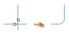
Grips are displayed when you select an object without starting a command. Grips are
often handy for light editing. For example, the line below accidentally snapped to
the wrong endpoint. You can select the misaligned line, click on a grip and then click
to specify the correct location.

By default, when you click a grip, you automatically start in **STRETCH** mode as
indicated in the Command window. If you want to explore other ways of editing objects
with grips, press Enter or the Spacebar to cycle through several other editing modes.
Some people perform most editing operations using grips.
nonyms for modifying at Thesaurus.com with free online thesaurus, antonyms, and definitions. Dictionary and Word of the Day.modifying im Englisch-Deutsch-Wörterbuch dict.cc.modifying im Online-Wörterbuch dict.cc ( Deutschwörterbuch).modifying. ۱ : to make changes in modify a plan. 2 : to lower or reduce in amount or scale In a little while familiarity modified their fears … — Mark Twain, Tom …modifying. present participle of modify; Altering. Derived terms[edit]. self-modifying. Retrieved from …modifying query. Element Detail. clearAutomatically. public abstract …modifying state when attempting to increase allocated storage?modifying' designed for tablets and mobile devices. Possible languages include English, Dutch, German, French, …modifying' in LEOs Englisch ⇔ Deutsch Wörterbuch. Mit Flexionstabellen, Aussprache und vielem mehr.