Controls many of the settings in the plotter configuration (PC3) file.
Click the icon for any of the nodes to view and change its settings.
When you change a setting, your changes appear in angle brackets (< ) next to the
setting name. A check mark is also displayed over the icon of the node with a changed
value.
Only the settings available for the configured device are displayed in the tree view.
In addition, you might not be able to edit some settings if the device handles the
setting through Custom Properties or doesn’t support the capability.
The following options are displayed.
Specifies a paper source, size, type, and destination. Available settings depend on
the supported features of your configured plotter. For Windows system printers, you
must configure the media settings using the Custom Properties node.
Specifies the paper source and size.
Displays a list of the media types supported by the plotter configuration.
Determines double-sided printing and binding margin. Binding margin options are available
only for plotters that support duplex printing.
Displays a list of available media destinations for the configured plotter, such as
collating, cutting, and stapling. These options are available only for plotters that
support this function.
Controls the specific pens in the pen plotter. The lower pane of the Device and Document
Settings tab displays a table used to describe the color, width, and speed of each
pen in the plotter.
The physical pen information cannot be detected automatically; you must provide this
information for your pen plotter under Physical Pen Characteristics.
Specifies settings for pen plotters.
To plot your drawing correctly on a pen plotter, you need to provide information about
the pens in your plotter. For each pen in your plotter, specify a color and width.
To optimize pen performance, you can specify a speed.
This information is required; the physical pen information cannot be detected automatically.
Specifying pen characteristics here doesn’t replace the pen tables you might have
imported from PCP, PC2, or CFG files from AutoCAD Release 14, AutoCAD LT آ® ۹۸, or earlier releases. For more information about importing these settings, see
“Change Plot Style Settings,†in the User’s VCade.
Specifies settings for printing vector graphics, raster graphics, and TrueType text.
Depending on the capabilities of the plotter, you can modify color depth, resolution,
and dithering. You can select either color or monochrome output for vector drawings.
When printing raster images on a plotter with limited memory, you can improve performance
by making some changes to the quality of the printed output. If you use a nonsystem
plotter that supports varying amounts of installed RAM, you can provide that information
to improve performance.
Provides the program with the amount of total memory (RAM) installed on a nonsystem
plotter. This option is only available for nonWindows system printers that accept
optional memory. If your plotter has extra memory, specify the total amount of memory.
Provides options for specifying the color depth, resolution, and dithering of vector
output. Some of the Vector Graphics options are closely interrelated; changing an
option can affect other available options.
Specifies trade-offs between plotting speed and output quality when plotting raster
objects on raster devices. If you reduce the image quality, you increase output speed.
If your system resources are limited, reducing image quality can reduce the chance
of running out of memory while plotting.
On Windows system printers, specifies whether to plot TrueType text as a graphic image
or as text.
Plotting as a graphic guarantees that the text is printed as displayed, at the expense
of slowing down the plotter and using more memory. Plotting as TrueType text prints
faster and uses less memory; the plotter may use a different font for printing.
On raster plotters, controls the appearance of lines that cross. Merge control is
not effective if your plotter is configured to plot everything as black or if you
are using PostScript language.
Merge control may appear as an option for system printers that do not actually support
the feature. Please check your printer’s documentation to determine if merge control
is supported.
Modifies the device-specific properties for the plotter configuration. The settings
for each plotter vary. If the plotter manufacturer has not included a Custom Properties
dialog box for the device driver, the Custom Properties option is not available.
For some drivers, such as ePlot, this is the only tree view option that is displayed.
For Windows system printers, most of the device-specific settings are made in this
dialog box. For more information about the custom properties settings for your device,
choose Help in the Custom Properties dialog box.
Sets pre-initialization, post-initialization, and termination ASCII text plotter strings,
which send commands to a plotting device before and after the program initializes
the device and after plotting is complete.
If you are plotting to an unsupported plotter in emulation mode, you can specify ASCII
text initialization strings that prepare the plotter for printing, set device-specific
options, and restore the plotter to its original state. You can also use initialization
strings to turn on or off a plotting device feature that is not supported by the program.
The text string is sent literally, except for a back slash (). Use a back slash followed
by a three-digit number (taken from the ASCII table), for example, 027, to specify
binary (unprintable) characters such as the escape character. 027 is interpreted and
sent as a single character whose value is 27. The number 27 is the escape character.
For example, 27%-12345X PJL ENTER LANGUAGE = PostScript10 sends an HP PJL command
to a dual-language laser printer before it’s initialized and switches the printer
into PostScript mode. The 027 sends an escape character and the 010 sends a line feed
character. The remainder of the text string is sent literally. It is best to use three
decimal digits for binary characters, so you’ll need to add leading zeros as necessary.
Initialization strings should be used by advanced users only.
Forces a plotter to emulate another plotter by sending a pre-initialization ASCII
text string to the plotter before it is initialized.
Use a back slash followed by a three-digit number (taken from the ASCII table), for
example, 027, to specify binary (unprintable) characters such as the escape character.
Sets a device-specific option that is not supported elsewhere in the program. Specify
a post-initialization ASCII text string that is sent to the plotter after it is initialized.
Use a back slash followed by a three-digit number (taken from the ASCII table), for
example, 027, to specify binary (unprintable) characters such as the escape character.
Restores the printer to its original state after plotting. Specify a termination ASCII
text string that is sent to the plotter after plotting is complete.
Use a back slash followed by a three-digit number (taken from the ASCII table), for
example, 027, to specify binary (unprintable) characters such as the escape character.
Attaches a PMP file to the PC3 file, calibrates the plotter, and adds, deletes, revises,
or filters custom paper sizes. You can also modify standard paper sizes. This node
accesses the Plotter Calibration and Custom Paper Size wizards. If the plotter you
are using has been calibrated, a Plotter Model Parameter (PMP) file contains that
calibration information. If the PMP file is not already attached to the PC3 file you
are editing, you must create that association so you can use the PMP file. If the
plotter was calibrated from within the Add-a-Plotter wizard while creating the current
PC3 file, the PMP file is already attached. Use the PMP File Name option under User-defined
Paper Sizes & Calibration to attach a PMP file to, or detach the PMP file from, the
PC3 file you are editing.
Creates a customized paper size or changes the printable area of a standard or nonstandard
paper size.
With the Custom Paper Size wizard you can create a new paper size, or select from
a list of available paper sizes (from a PMP file) if the plotter is not a Windows
system printer. If the plotter is a Windows system printer, use Custom Properties.
Each plotter has a maximum printable area determined by where it grips the paper and
how far the pen shuttle can reach. If you are creating a paper size that is larger
than the paper sizes offered in the Plotter Configuration Editor, verify that the
plotter is capable of plotting the new dimensions.
For Windows system printers, you can change the paper size settings and create custom
paper sizes only in the Custom Properties dialog box.
Adjusts the printable area for standard paper sizes to match the printer’s capabilities.
(You can’t create custom paper sizes for Windows system printers using the Plotter
Configuration Editor.)
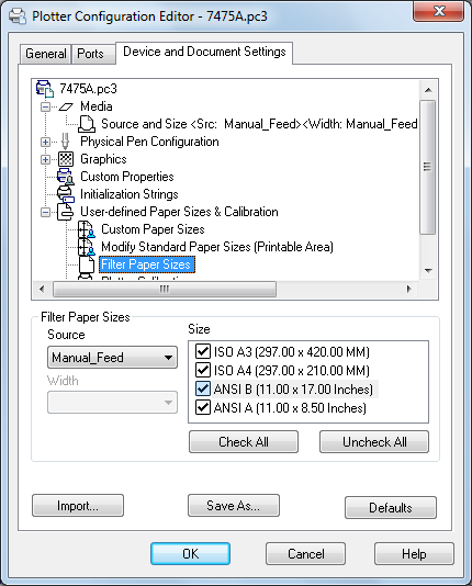
Filters the list of paper sizes displayed for the plotting device selected in the
Plot and Page Setup dialog boxes. The list of paper sizes is displayed on the Plot
Settings tab in the Plot dialog box and on the Layout Settings tab in the Page Setup
dialog box.
Select the paper sizes you want to display for this device.
Starts the Plotter Calibration wizard. If you need to correct scaling discrepancies,
you can adjust the plotter calibration using the Plotter Calibration wizard. See “Calibrate
Plotters and Work with Custom Paper Sizes†in the Driver and Peripheral VCade.
You should perform a plotter calibration only if your drawings must be exactly to
scale and your plotter or printer produces inaccurate plots. Plotter Calibration causes
the program to rescale all plots sent to your plotter. If your plotter provides a
calibration utility, it is recommended that you use it instead of the utility supplied
with this program.
Attaches a PMP file to or detaches a PMP file from the PC3 file you are editing. Use
the Detach button to break the association between the PMP file and the PC3 file.
Imports file information from earlier versions of the program. If you have a PCP or
PC2 file from an earlier version, you can import some of the information in those
files into a PC3 file. PC3 files store plotter name, port information, pen optimization
level, paper size, and resolution.
Saves a PC3 File to a new file name.
Restores the settings on the Device and Document Settings tab back to the default
settings.
spe list of paper sizes is displayed on the Plot Settings tab in the Plot dialog box and on the Layout Settings tab in the Page Setup dialog box. Select the paper sizes you want to display for this device. Check All: Hides all the paper sizes for the device. Uncheck All: Displays all the paper sizes for the device.Plotter Configuration Editor with any of the following methods: Double-click a PC3 file in Microsoft ® Windows ® Explorer or right-click the PC3 file and click Open. Choose Edit Plotter Configuration from within the Add-a-Plotter wizard. Choose Properties in the Page Setup dialog box.Plotter Configuration Editor, on the Device and Document Settings tab, you can change many of the settings in the configured plot (PC3) file. Only the …Plotter Configuration Editor provides options for modifying a plotter's port connections and output settings … The Plotter Configuration Editor contains three tabs: … Device and Document Settings. … About Setting Up Plotters and Printers …Plotter Configuration Editor is displayed. In the Device and Document Settings tab, click the Custom Properties node in the tree. In the Access Custom …plotter driver in AutoCAD, do the following to add a custom … In the Plotter Configuration Editor, click the Device and Document Settings tab.plotter configuration you want to modify. In the Plotter Configuration Editor, click the Device and Document Settings tab. Double-click …Plotter Configuration Editor, Device and Document Settings tab, double- click … Paper Sizes & Calibration to display the calibration and paper size settings.Plotter Configuration Editor Add a Custom … In the Plotter Configuration Editor, Device and Document Settings tab, …plotter configuration you want to modify. In the Plotter Configuration Editor, click the Device and Document Settings tab. Double-click …